FMX - Model Rocket Beacon


This project is based Jerry Baumeister FMX1 at https://www.jbgizmo.com/page30.htm

FMX is model rocket beacon that transmits a beep every 1-2 seconds
and transmits the station call sign in Morse code every 30 seconds.
The transmission is in the amature radio 2 meter band.
It runs on two CR1632 (3 volt lithium) batteries, and supports about 4 days of opperation.

You can order the PCB from OSHPARK

The PCB is 57.2mm X 18mm which is the diameter of an A B or C sized rocket engine.
This means it will easily fit in a standard rocket kit which typically has 22mm diameter tube.

Remember to add fireproof wadding before adding your
transmitter, parachute, and nose cone.

Order from OSH Park

Download this page as a PDF
Download the zipped gerber files
Download the eagle circuit
Download the eagle board
Download the assemby code
Download the compiled hexcode
Note: this code uses FMX instead of the call sign.

How to complete this project
Top
Bottom

Parts
Label Part Description
R1 Resistor 10K 1/8 watt mouser: 299-10K/REEL-RC
R2 Resistor 100K 1/8 watt mouser: 279-LR2F100K
C1 Capacitor .001 uF mouser: 581-AR30HC102K4R
C2 Capacitor 22 pF mouser: 81-RCE7U2J220J2M1H3A/td>
C3 Capacitor 15 pF mouser: SR155A150KAA
C4 RCapacitor 15 pF mouser: SR155A150KAA
Q1 NTE107 digikey: 2368-NTE107-ND
Q2 NTE108 digikey: 2368-NTE108-ND
mouser: 610-PN918
Q3 49.152MHZ 3rd overtone crystal mouser: 695-HC49US-49.1-U
IC1 PIC12F675 I/P mouser: 579-PIC12F675-I/P
L1 0.68 uH inductor mouser: 652-78FR68K-TR-RC
L2 4 turns #22 magnet wire wound on 1/8" drill-bit mouser: 566-8051
8 pin DIP socket mouser: 110-41-308-41-001000
BAT1 CR1632 battery holder mouser: 614-HU1632-LF
BAT2 CR1632 battery holder mouser: 614-HU1632-LF
Battery Two CR1632 mouser: 614-CR1632
Atenna 12" #20 or #24 solid conductor wire
counter-pole 12" #20 or #24 solid conductor wire

Assembly Start by installing the 8 pin dip socket. Note the top with the notch must face the battery side of the circuit, as shown on the silk screen outline. Solder the four corners then the inner pins. Next install the Transistor Q2, NTE108 with the flat side facing the 8 pin DIP socket, as shown on the silk screen outline. Carefully bend the middle pin backwards to fit the hole pattern. Trim the leads after soldering for this component is finished. Next install R1, the 10K Resistor. Verify it is colored brown / silver / blue / gray / red. Install R2. Choose either: Verify the 100K Resistor is colored gray / gray / brown / gray. Next install Q3, the crystal. It looks like a metal silver elongated top hat. Install L1, a Fixed Inductor RF CHOKE 0.68μH. Verify it is colored purple / blue / purple / gray. You will need to make L2 out of 3.25 inches of 22 gage magnet wire. Using a knife carefully scrape the lacquer from the ends of the coil for about 1/2 inch. Next construct the coil (L2) by close winding 4 turns of the magnet wire on the shaft of a 1/8" drill bit shaft (or similar size item) and then slide the coil off of the drill bit shaft or form. The coils should be tightly wound. Solder this coil  on to circuit ensuring the bare copper is soldered to the circuit. Next install Q1, the Transistor NTE107 with the flat side facing away from the 8 pin DIP socket, as shown on the silk screen outline. Next install the Resistors C1, C2, and C3.

Also ONLY include C4 if R2 is a 10K Resistor.

C1 is a 1000pF Capacitor. C2 is a 22pF Capacitor. C3 is a 15 pF Capacitor.

** only install C4 if R2 is a 10K Resistor**C4 is also a 15 pF Capacitor**

Install the two battery holders, one on each side of the circuit board. Next, use 12 inches of 20 - 24 gauge common "hook-up" wire as the antenna and counterpoise. These attach to the larger holes at either side of the circuit board labeled “ANT” and "CP". Install the two pin jumper near the battery holder. Lastly install the PIC microcontroller Chip into the 8 pin DIP socket, ensuring that the top with the notch is facing the battery as indicated by the DIP socket. You may have to to bend the pins of the chip slightly to make them perpendicular such that they fit in the DIP socket. If you need to compile and/or program the PIC, do so prior to installing into the DIP socket. This can be done with MPLAB IDE and a PICkit3. Detailed instructions follow. Source code and hex files can be found at: www.schiller.net/jason/fmx/

Testing Install the two batteries and jumper JP1 to turn the transmitter on. Confirm you hear beeps, the call sign in Morse code, and that the transmitter drops between beeps. Note that due to variations in crystal frequency the actual frequency of the transmitter will be in the range of 147.455 and 147.560 Mhz. If the transmitter is continuously transmitting, you need to add C4 to your circuit. Test the transmitter by throwing it up into the air and allowing it to fall to the ground. Confirm the transmitter is still functioning.

Coating the circuit Consider painting the circuit with two coats of protective polyurethane. Do not coat the batteries, the battery terminals, or jumper. This will help to protect the circuit from the explosion which blows off the nose cone and deploys the parachute.

Attaching the beacon The easiest way to attach the beacon is to run the shock cord through the two large holes in the circuit board. Add fireproof wadding to the rocket tube. Insert the circuit board followed by the carefully folded parachute. Lastly add the nose cone.

Tracking Tracking is best accomplished with a directional antenna such as a yagi. When that is not possible, use body fade to shield one direction from the antenna. Hold the receiver close to your stomach with the antenna pointing vertically. Slowly turn your body as you listen for the direction of the loudest and quietest beeps. The transmitter should be in the direction of the loudest beeps, or 180° away from where the beeping is the quietest. Walk in that direction, then take another reading.

Compiling To compile your own code with your callsign you will need to install:
Open MPLAB X IDE.

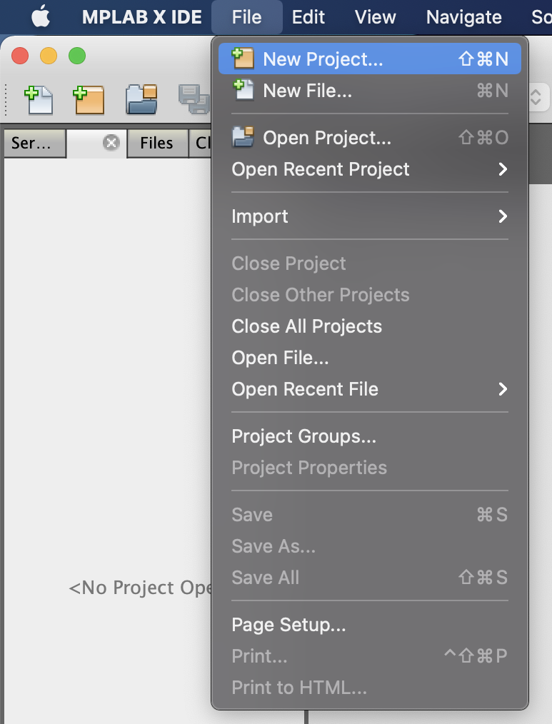
Start a new project:
select > File > New Project from the menu
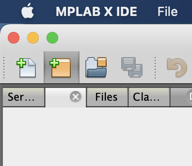
or click on the the new project icon
(yellow folder with a green plus)
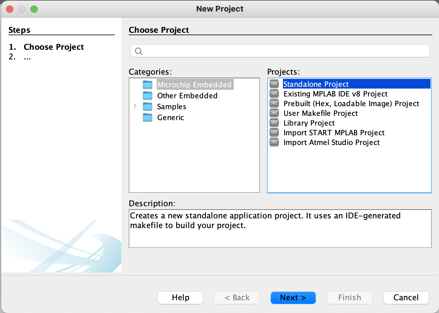
Choose new project catagory: Microchip Embeded
and project: Standalone Project
Then click the Next button.
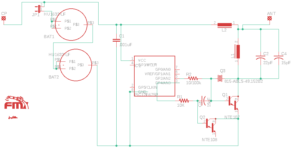
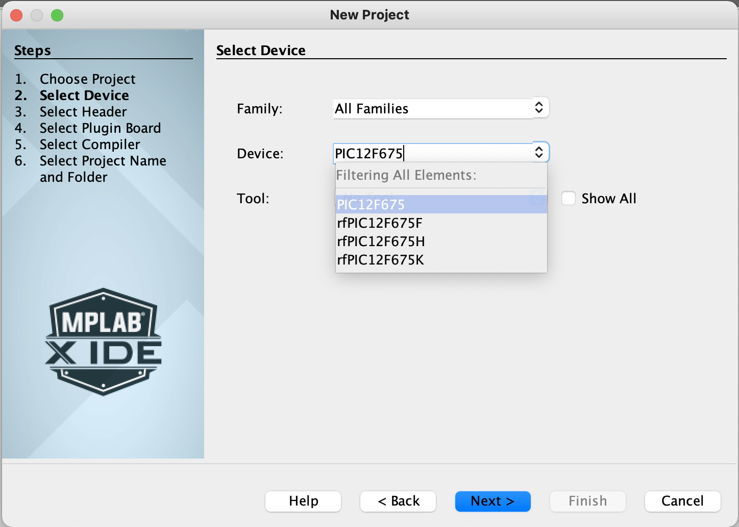
For device type the name of the chip "pic12f675".
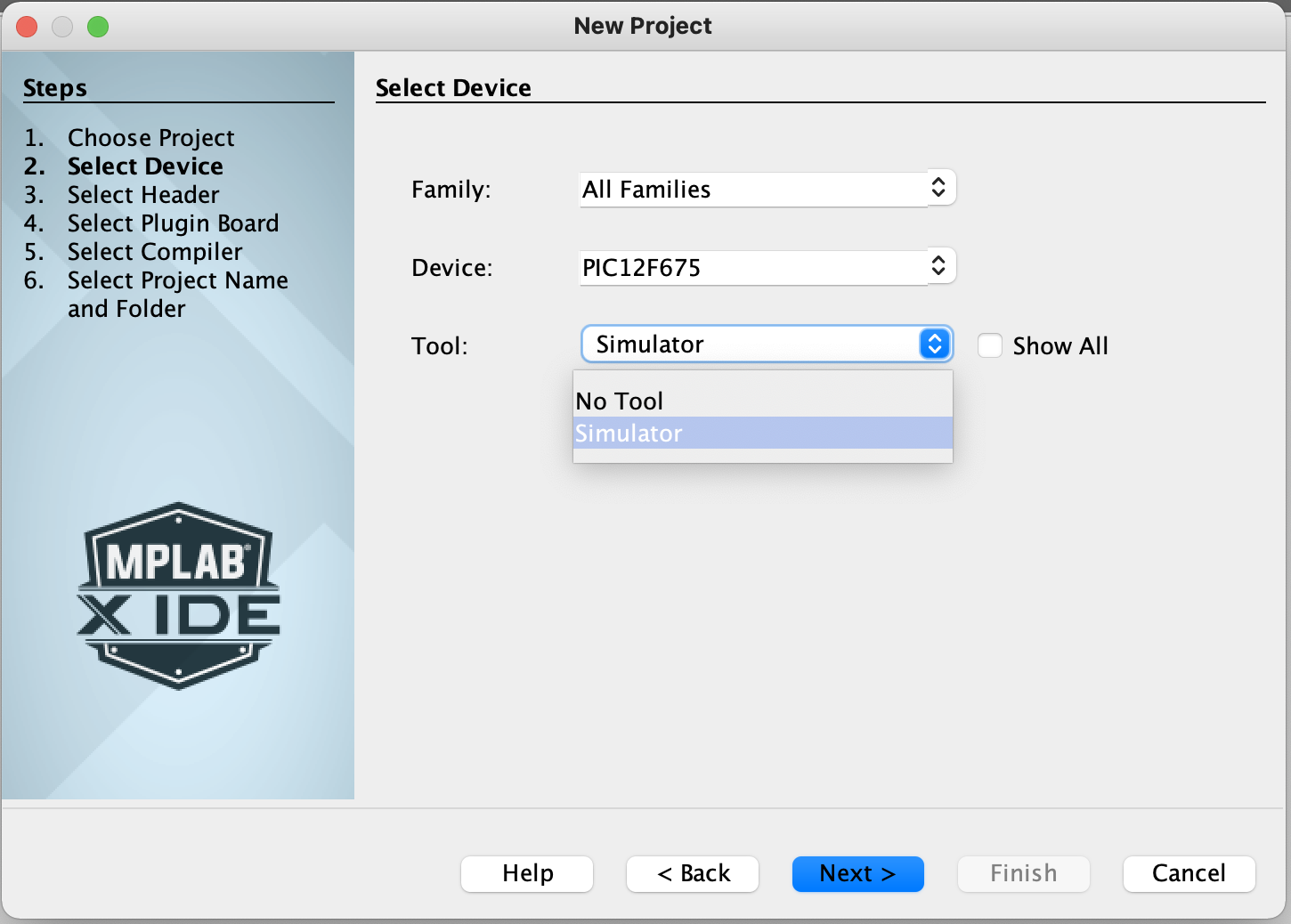
Then select simulator, and click the Next button.
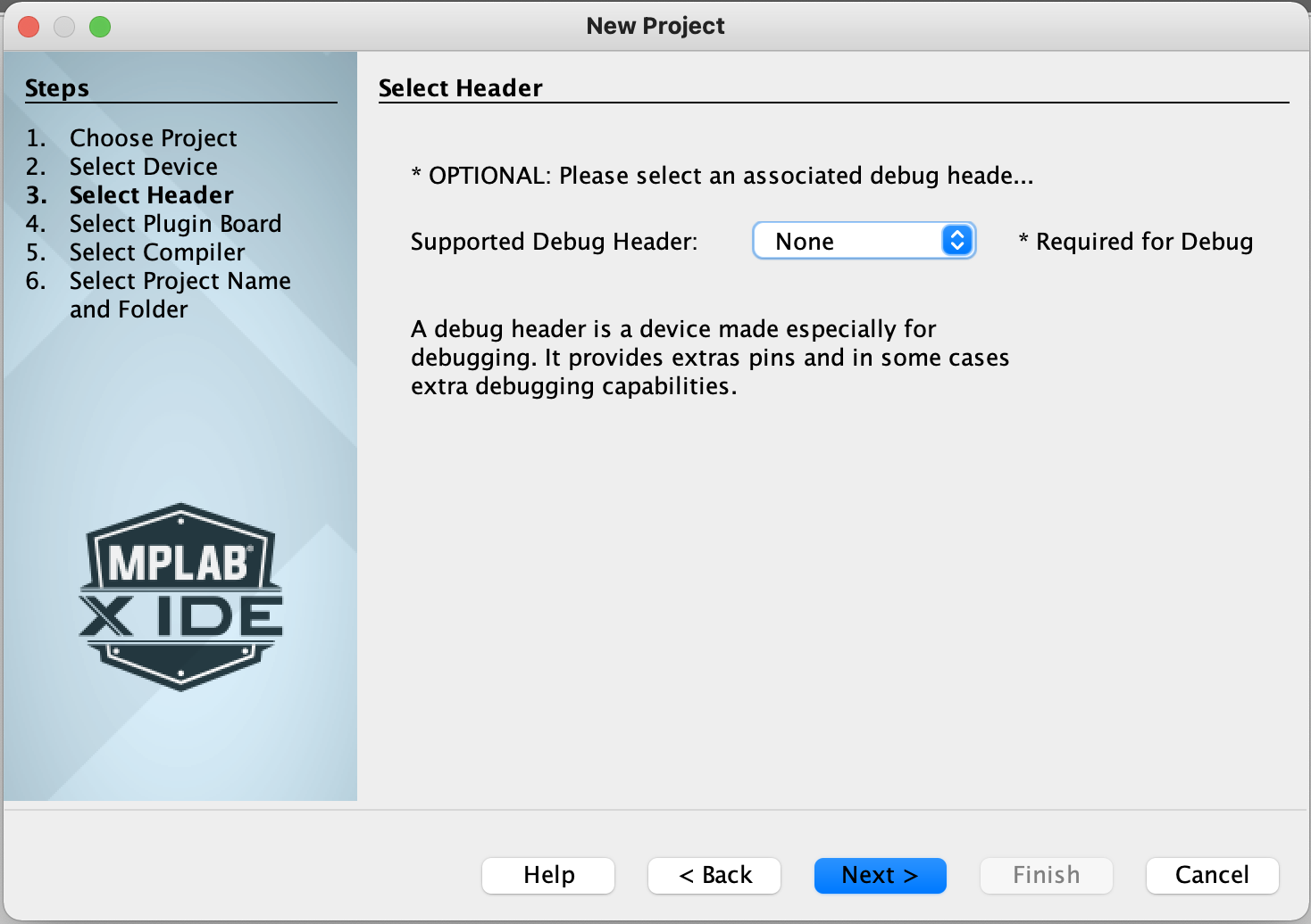
Choose no debug header: none.
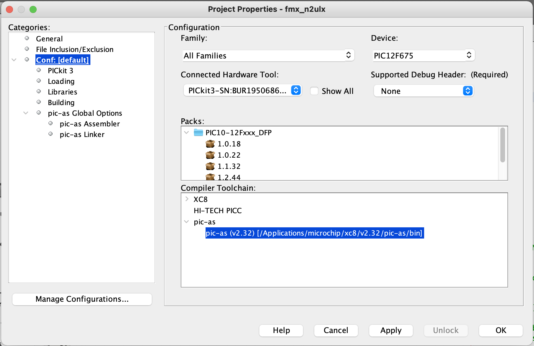
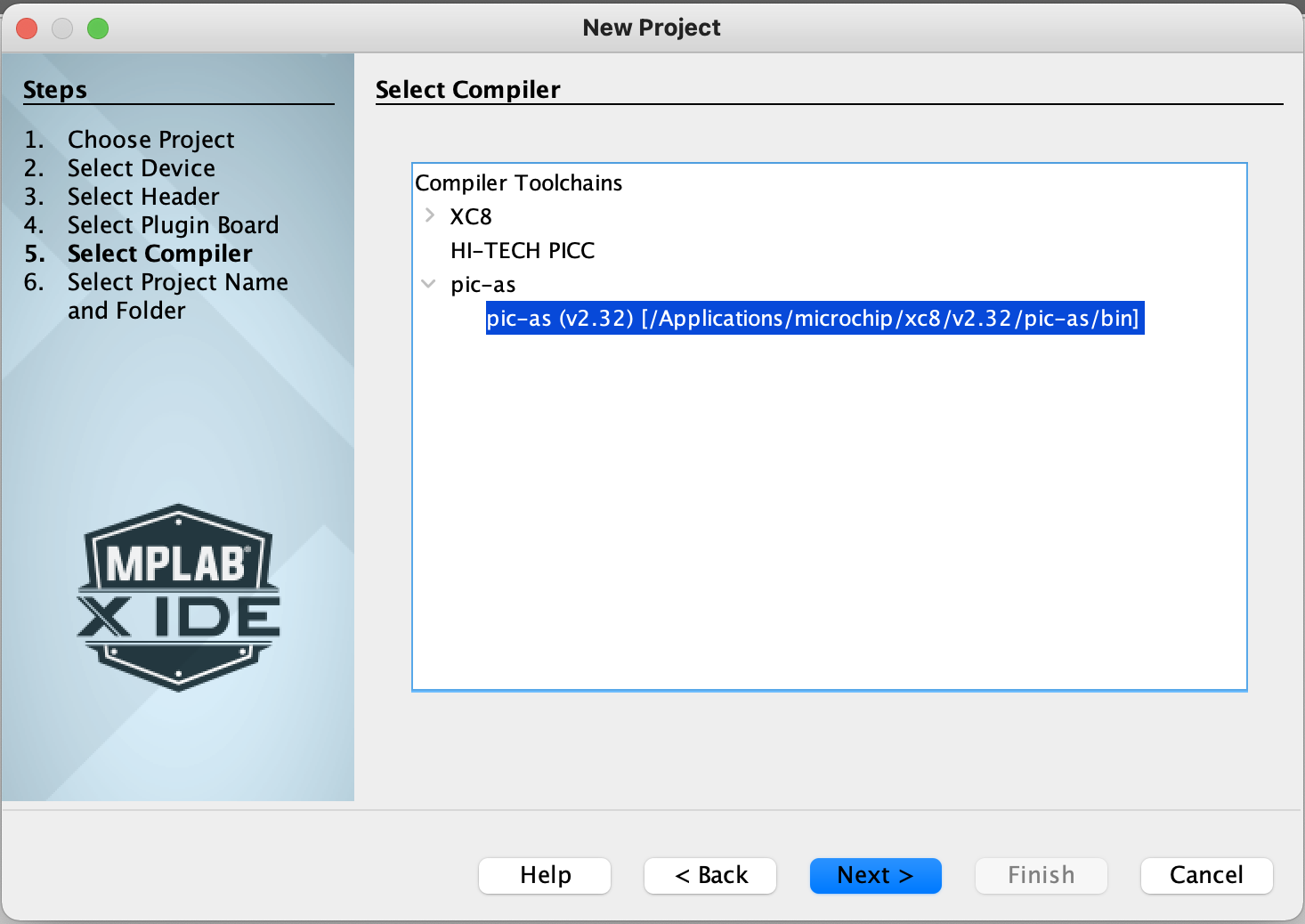
Select the compiler:
"pic-as (v2.32) [Applications/micrchip/xc8/v2.32/pic-as/bin]"
and click the Next button.
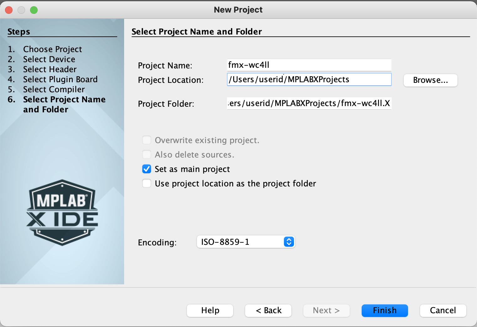
Select the project name.
Use fmx-<your_call_sign>.
In this example we use the call sign WC4LL,
and the project name fmx-wc4ll.
Click the Finish button.

By default the project is created under your home directory
and under a directory called MPLABXProjects.
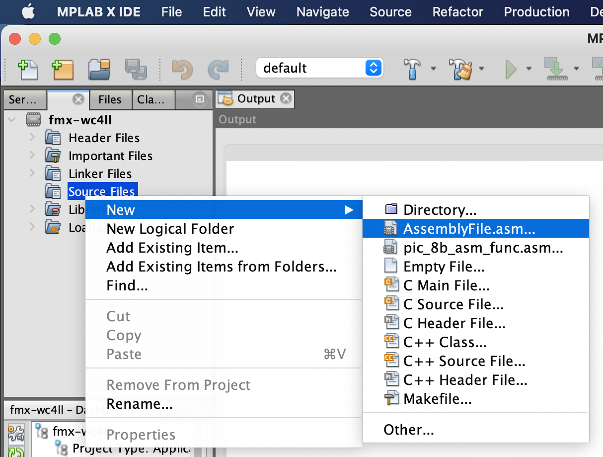
Right click on Source files.
Choose New > AssemblyFile.asm.
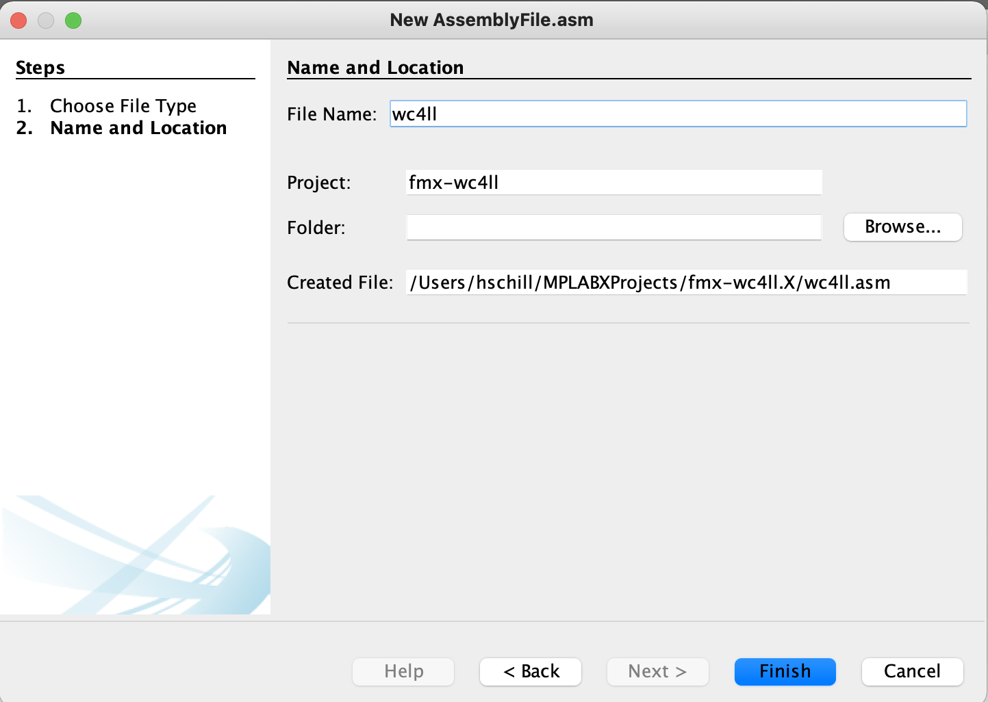
Name the file fmx-<Your_Call_sign>.
In our example we use fmx-wc4ll.
Click the Finish button.
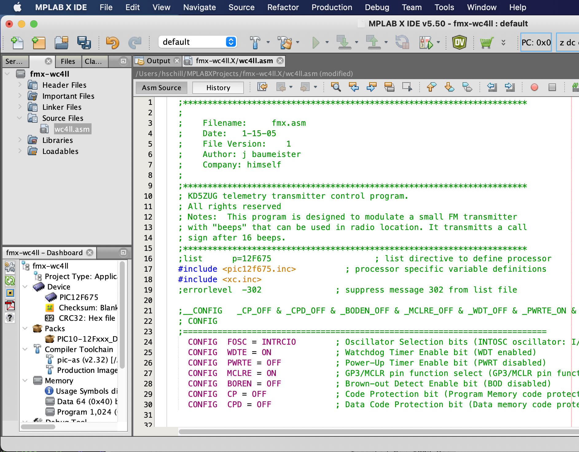
Paste in the raw text of the assembly code.
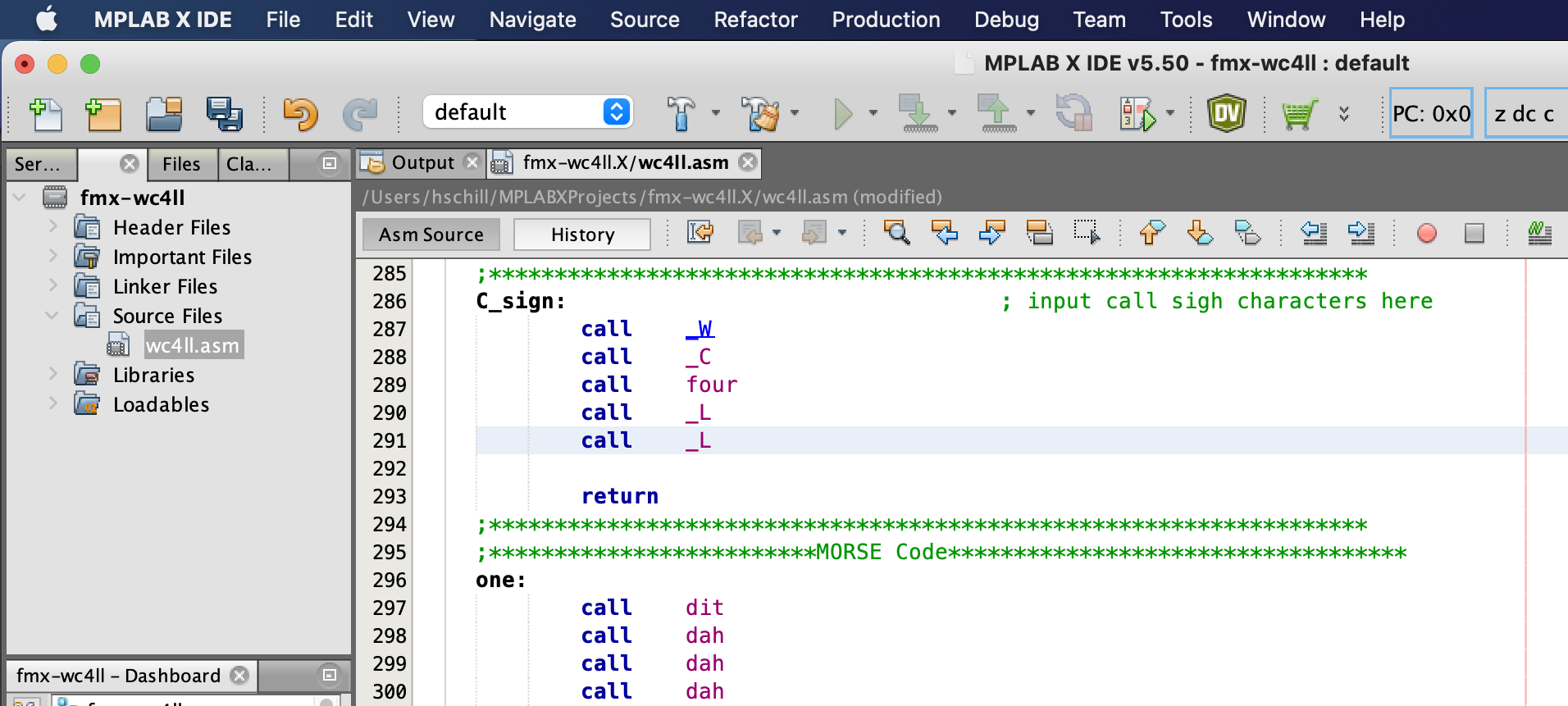
Scroll down to line 286 where the call sign is configured.
Replace the three lines: call _F
call _M
call _X

With your call sign. In this example:
call _W
call _C
call four
call _L
call _L
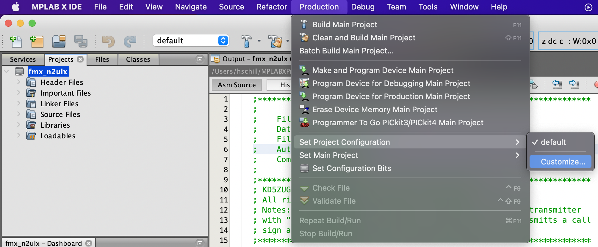
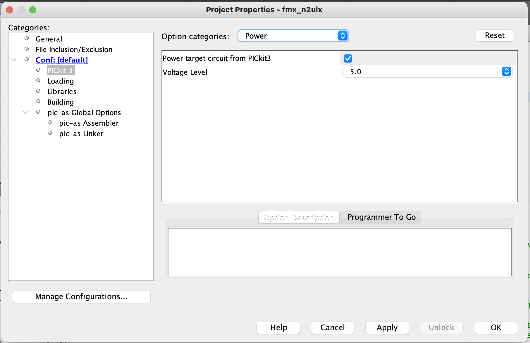
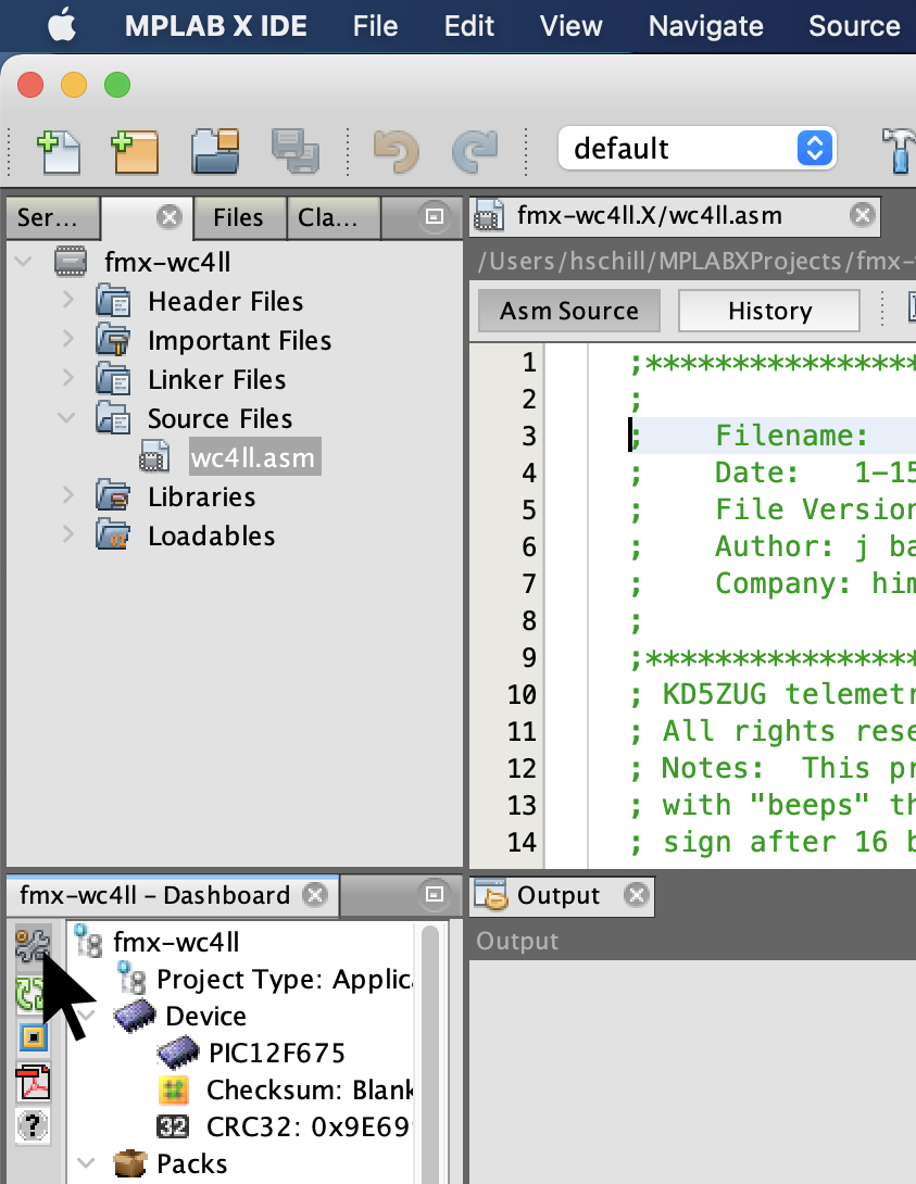
Click on the configure button
(a Wrench with a nut and bolt)
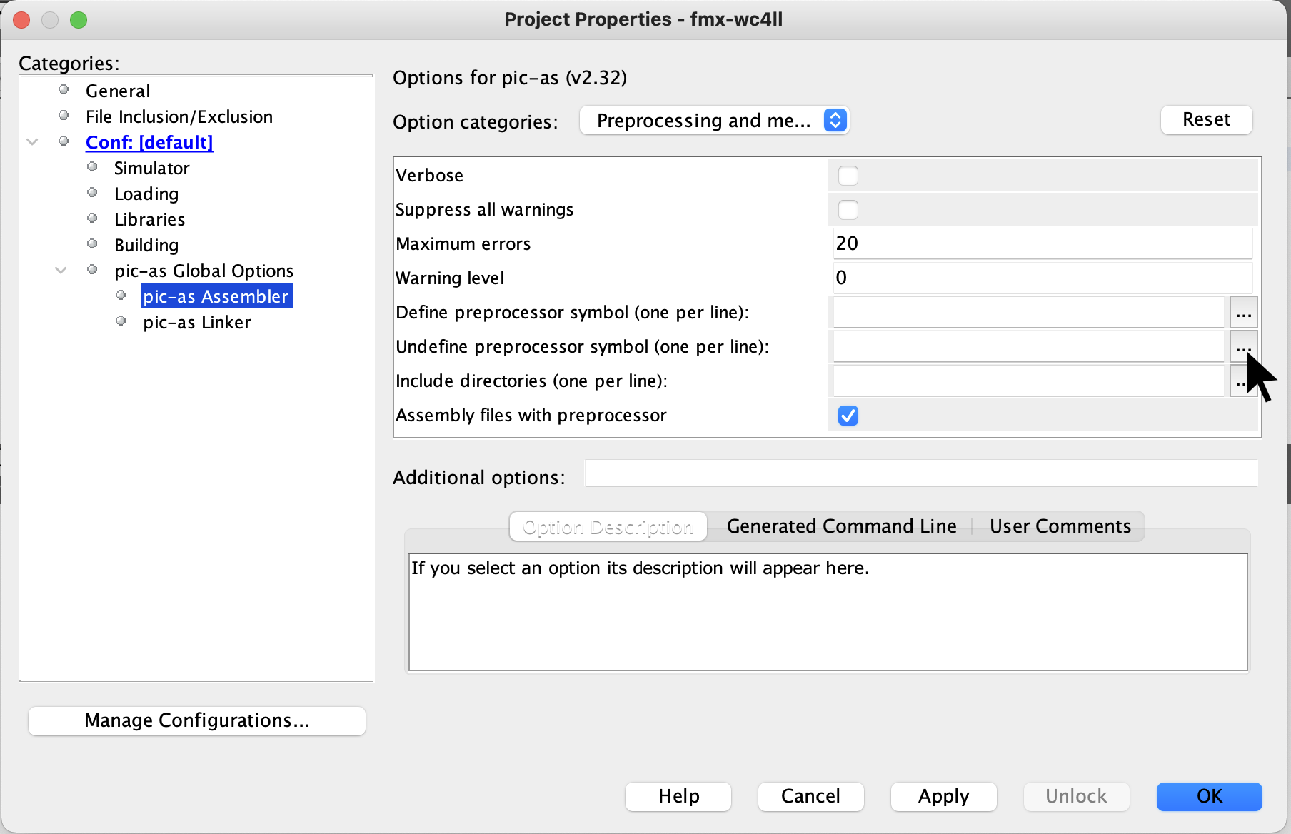
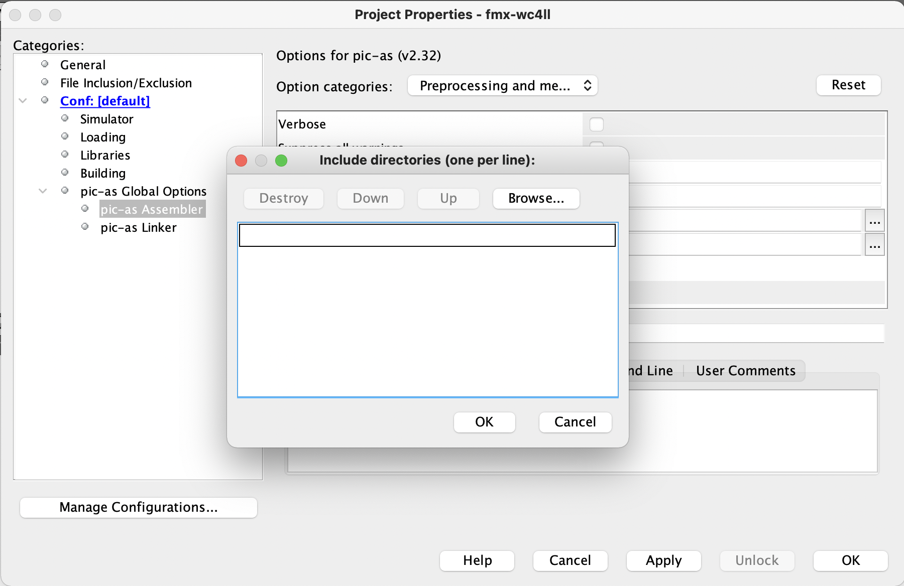
Click on pic-as Assembler.
And the include directories.
(the icon has three dots)
click the Browse... button.
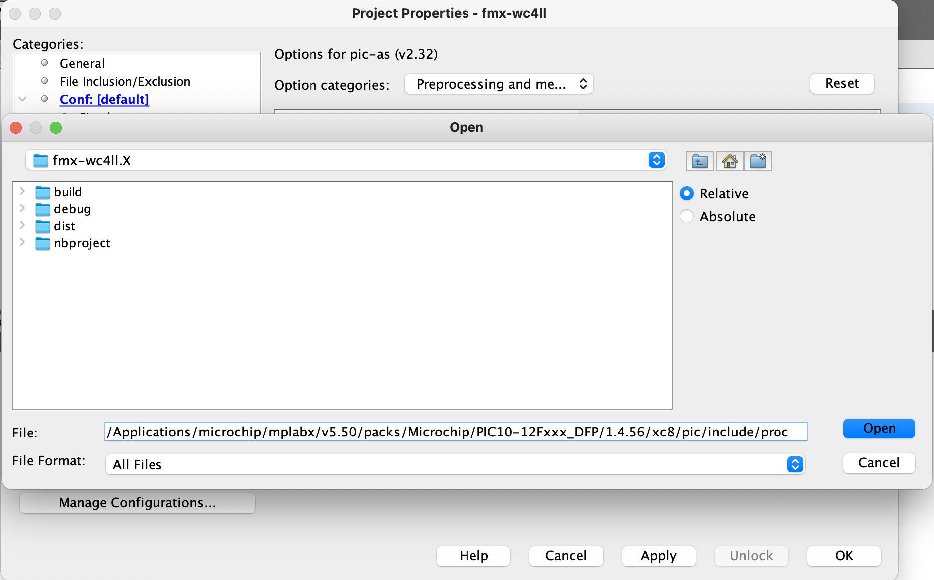
Set the include directory as:
/Applications/microchip/mplabx/v5.50/packs/Microchip/PIC10-12Fxxx_DFP/1.4.56/xc8/pic/include/proc
and click the Open button
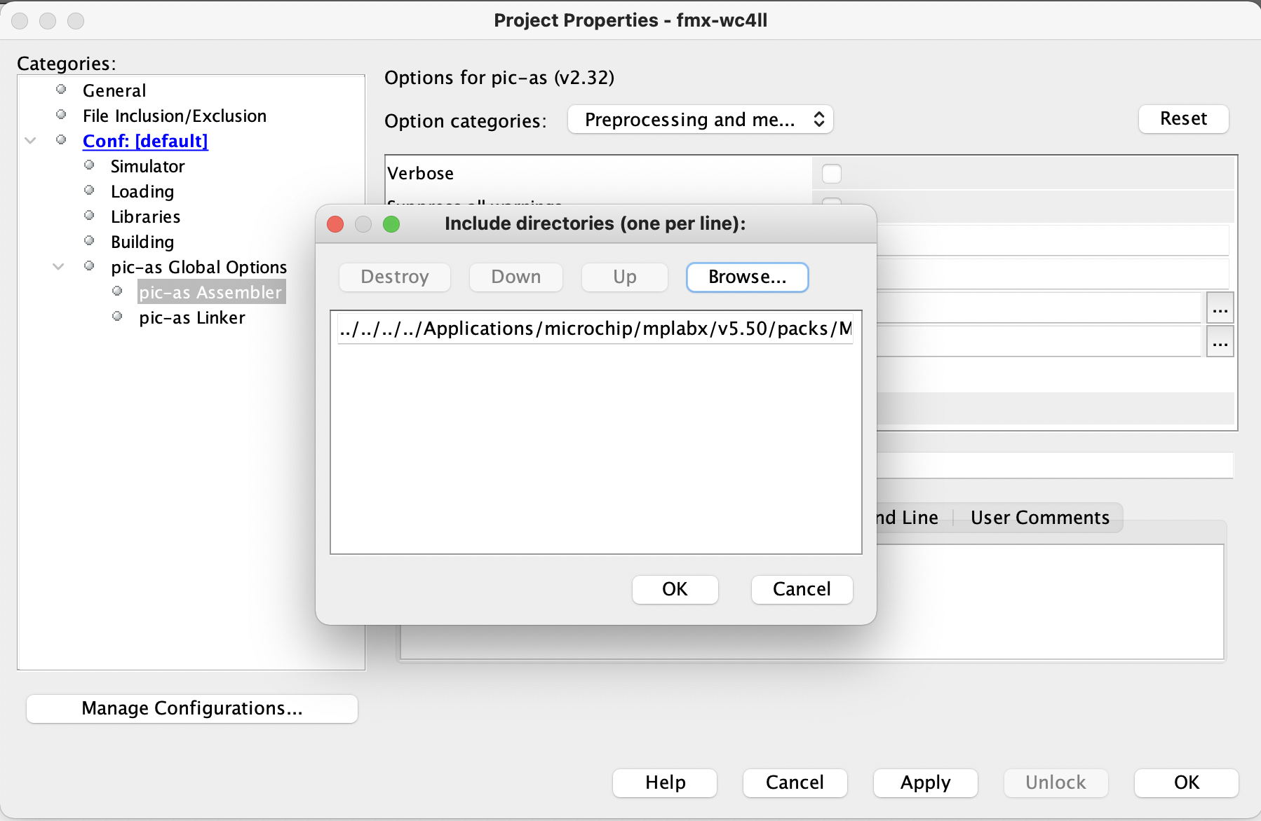
then click the OK button.
to accept the order of the newly configured path
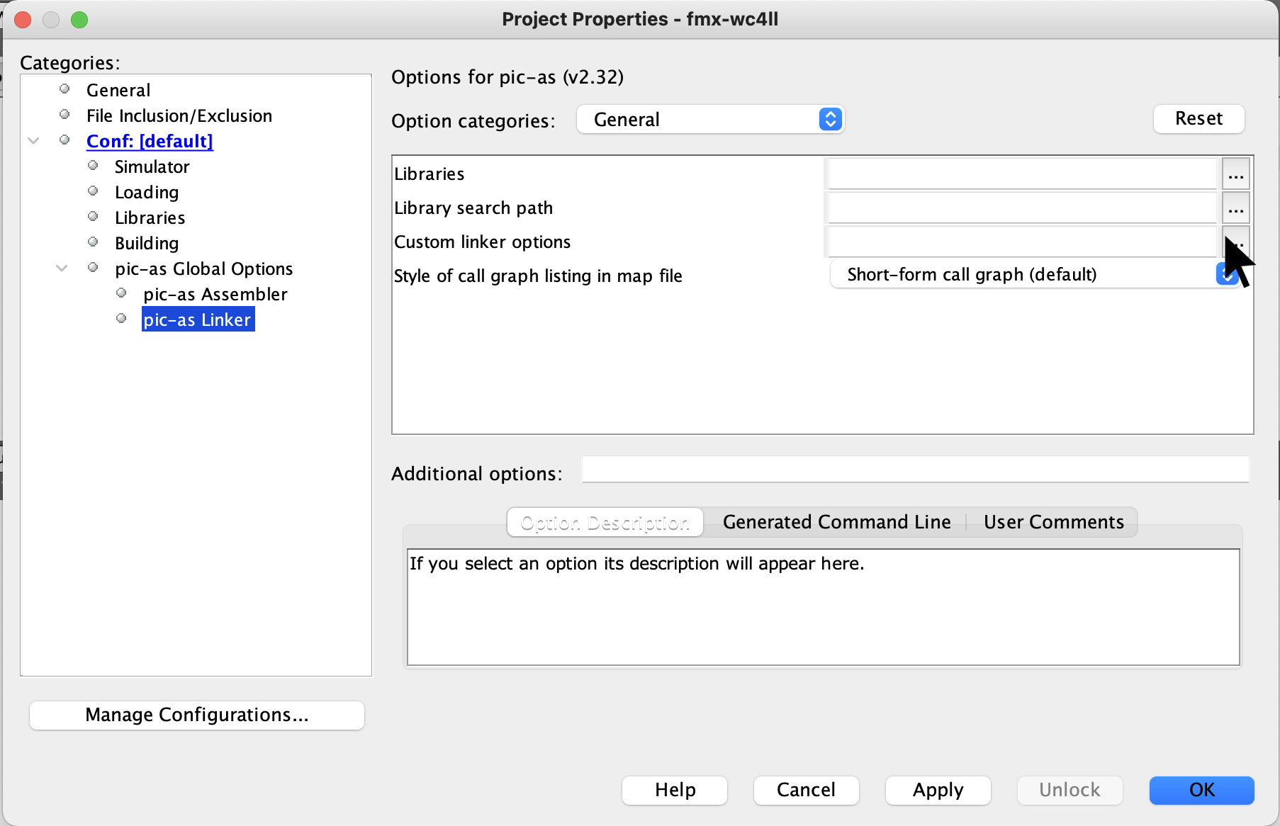
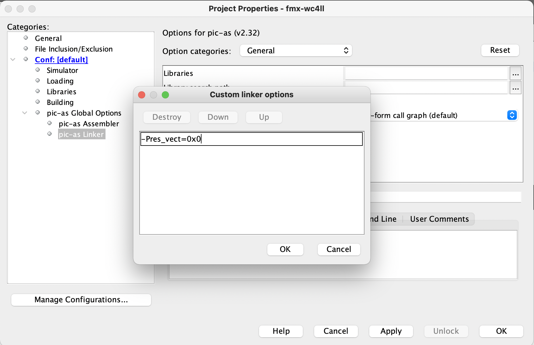
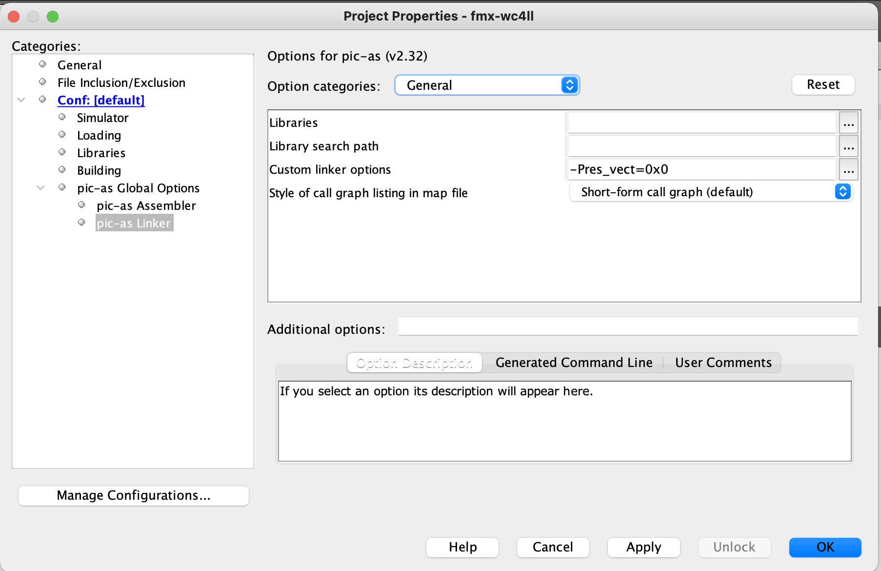
Click on pic-as Linker.
And the custom linker options.
(the icon has three dots)
set the customer Linker options to:
-Pres_vect-0x0
and click the OK button.
click the OK button.
to accept the newly configured changes.
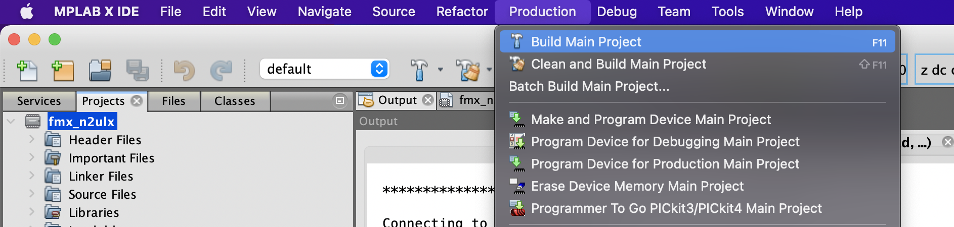
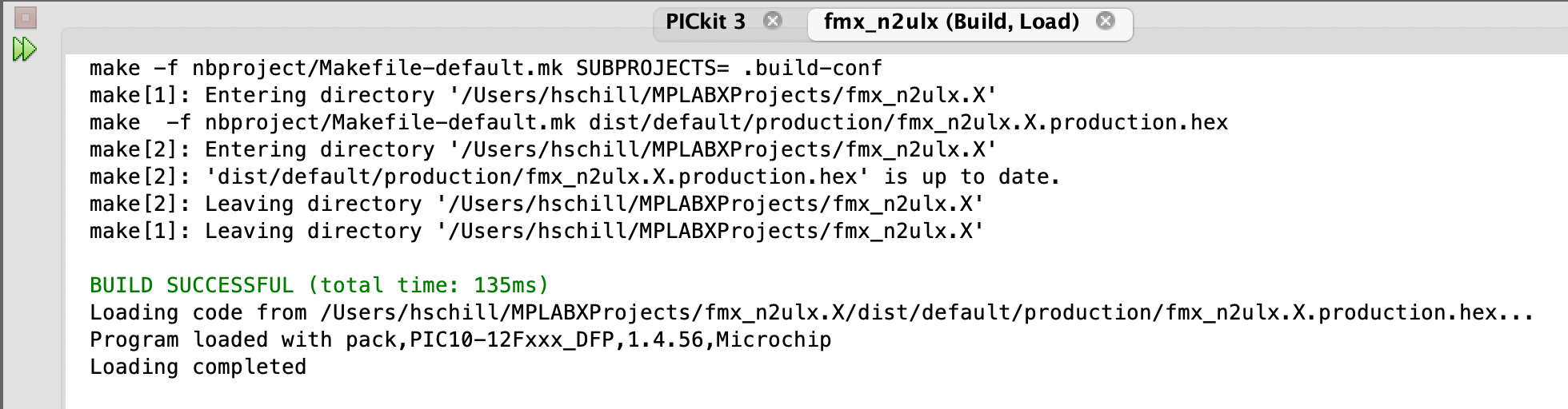
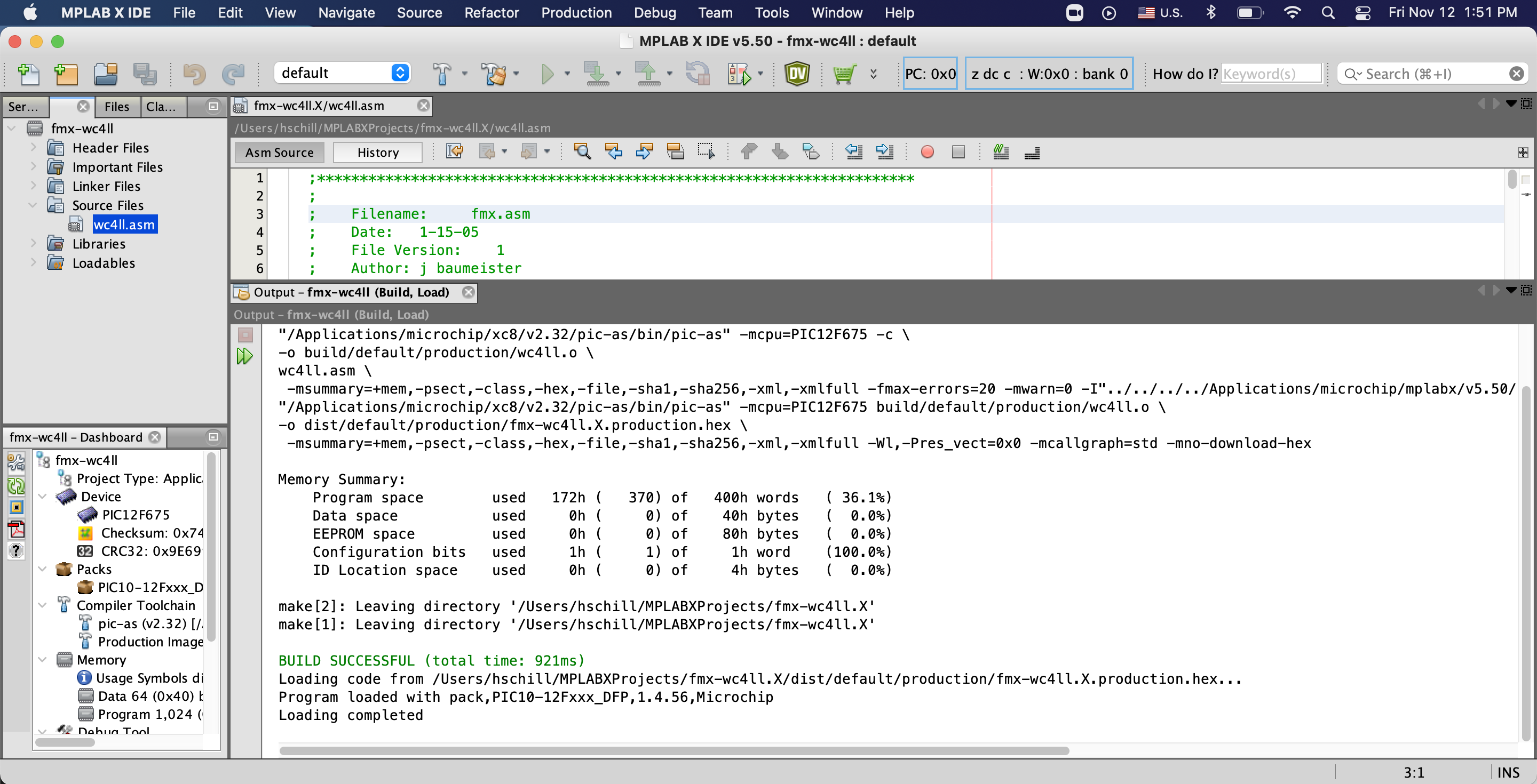
Now compile the code by clicking on the hammer icon
You can find the hex file inside your home directory at
MPLABXProjects/fmx-<YOUR_CALL>.X/dist/default/production
The file name will be fmx-<YOUR_CALL>.X.production.hex
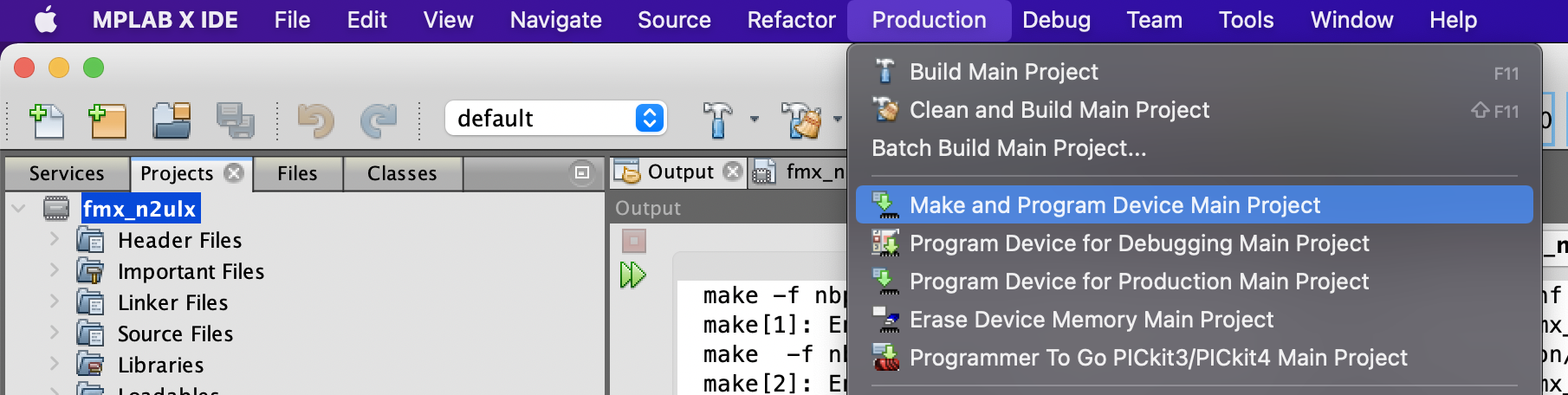
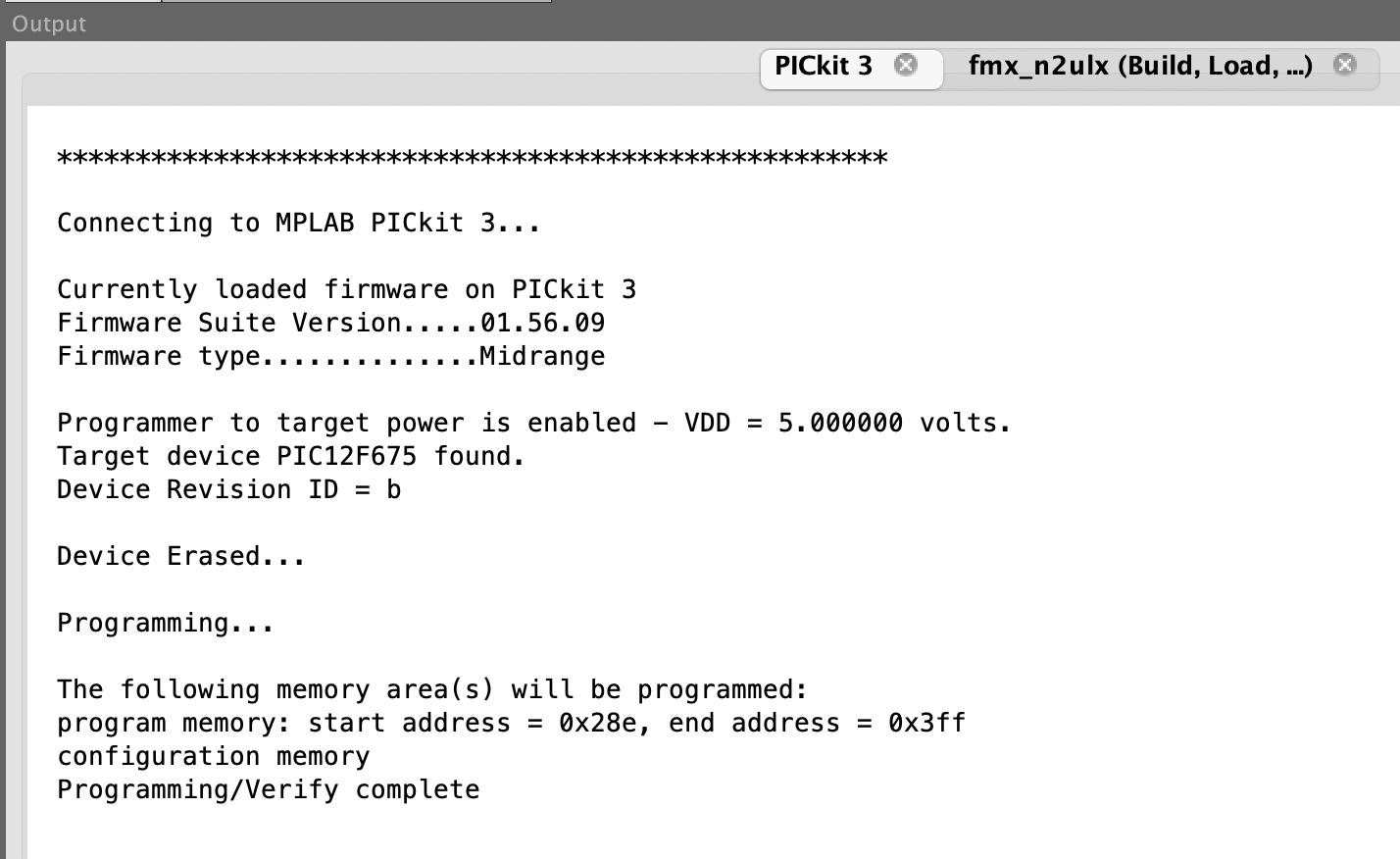
Now write the hex file to the PIC12F675 chip

Flashing
Open MPLAB X IDE.
Open your project.

Click on:
Production > Set Project Configuration > Customize
Click on the Category Conf [default]
And make sure PICKit3 is selected for the connected Hardware Tool
Click on the Category PICkit 3
Select Option Category: Power
Check the box for:
Power target circuit from PICkit3

Set the voltage level to 5.0 (or less down to 3.3)

Click the OK button
Now compile the program one last time
Click on Production > Build Main Project

OR click the hammer from the tool bar.
Check that the build is successful.
Lastly, program the chip.

Click on:
Production > Make and Program Device Main Project
OR click the icon of the green arrow download code to the chip.
Check that the programming was successful

Reference Images


Return to Schiller.net