![[Picture of NES mini]](images/NES-mini.png)
![[Picture of NES 72 pin connector]](images/72-pin.png) I had forgotten how annoying it was when the 72 pin Zero Insert Force
(ZIF) connector wouldn't line up just right with the cartridge.
The NES-001 has a hinged flap, with a front loading 72 pin Zero
Insertion Force (ZIF) connector. The NES was modeled to look like
VCR in line with it being branded as an "entertainment system" rather
than a game console. This why it was also sold with R.O.B. the
Robotic Operating Buddy to further distinguish it from game consoles.
I had forgotten how annoying it was when the 72 pin Zero Insert Force
(ZIF) connector wouldn't line up just right with the cartridge.
The NES-001 has a hinged flap, with a front loading 72 pin Zero
Insertion Force (ZIF) connector. The NES was modeled to look like
VCR in line with it being branded as an "entertainment system" rather
than a game console. This why it was also sold with R.O.B. the
Robotic Operating Buddy to further distinguish it from game consoles.![[Picture of NES connector on Aliexpress]](images/shenzhen.png)
![[Picture of NES connector on Aliexpress]](images/boil.png) Simply find an old pot that you no longer use for cooking, fill it
with water and your 72 pin connector and bring it to a rolling boil
for 20-30 minutes. This will not only clean the pins, but also bring
some of the more minor bent pins back into their original configuration.
Remember to allow it to fully dry prior to reinstalling it.
Simply find an old pot that you no longer use for cooking, fill it
with water and your 72 pin connector and bring it to a rolling boil
for 20-30 minutes. This will not only clean the pins, but also bring
some of the more minor bent pins back into their original configuration.
Remember to allow it to fully dry prior to reinstalling it.![[Picture of Blinking Light Win]](images/blw.png)
![[Picture of NES with edge conneaector]](images/edge-NES.png) I did find one example of an NES with an edge connector,
but it seems the owner has no plans of mounting the
connector in the console, as they are only interested in
playing a single game. This attempt was successfully
completed after I had already produced the NESedge.
I did find one example of an NES with an edge connector,
but it seems the owner has no plans of mounting the
connector in the console, as they are only interested in
playing a single game. This attempt was successfully
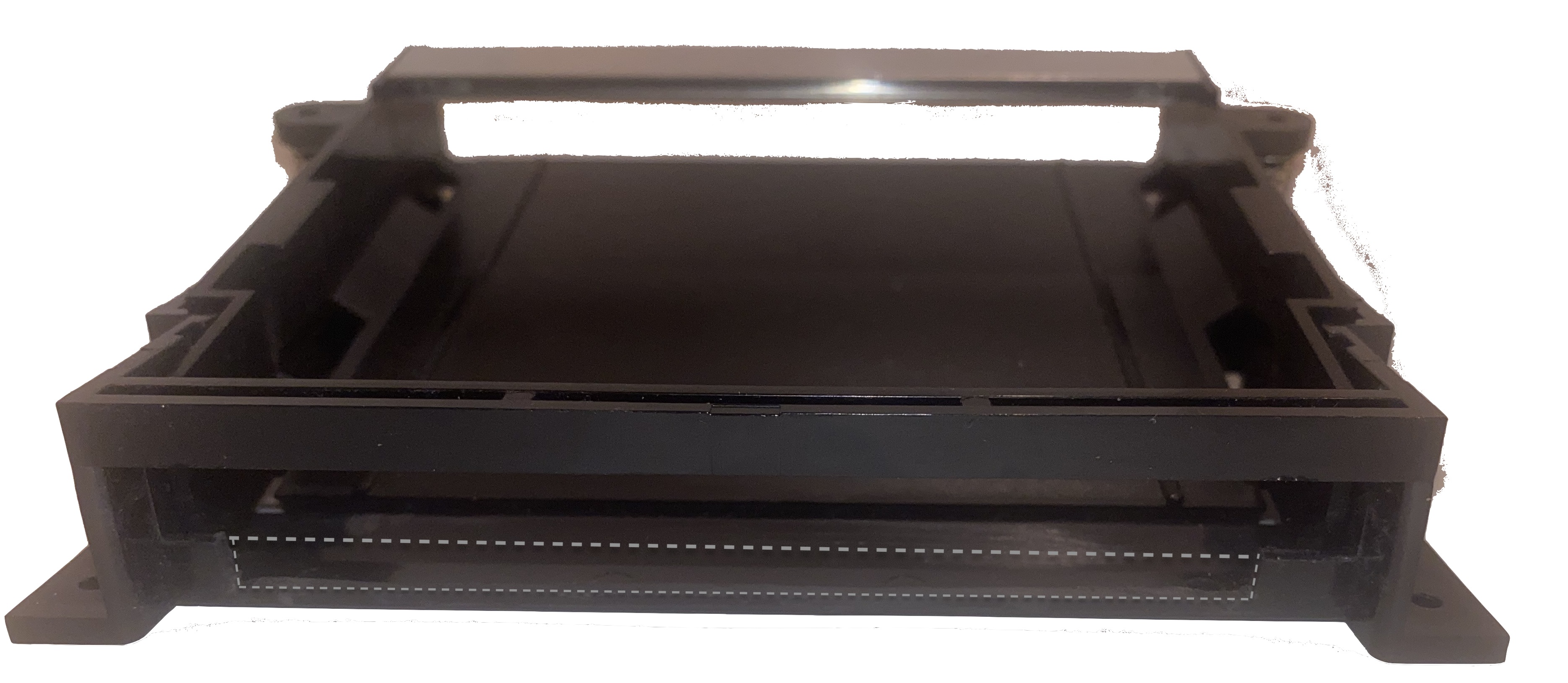
completed after I had already produced the NESedge.![[Picture of NES with edge conneaector]](images/fail-edge.png) Then there is this gem that was purchased from Goodwill.
It has an edge connector that is way too small in depth,
and is mounted with screws that further prevernt the
cart from being inserted all the way in. It also
prevents the cartridge tray from being able to be pushed
down.
Then there is this gem that was purchased from Goodwill.
It has an edge connector that is way too small in depth,
and is mounted with screws that further prevernt the
cart from being inserted all the way in. It also
prevents the cartridge tray from being able to be pushed
down.![[Picture of NES Toaster inside]](images/toaster-open.png) Which proved that an edge connector would function when connected
to the NES mainboard with 22 AWG solid-core wire. So I got inspired...
and set to thinking about how to make a better NES 72 pin connector.
Which proved that an edge connector would function when connected
to the NES mainboard with 22 AWG solid-core wire. So I got inspired...
and set to thinking about how to make a better NES 72 pin connector.
 I managed to meet all the requirements, but sadly I needed to trim away
most of the front part of the cartridge tray to make room for the edge
connector.
I managed to meet all the requirements, but sadly I needed to trim away
most of the front part of the cartridge tray to make room for the edge
connector.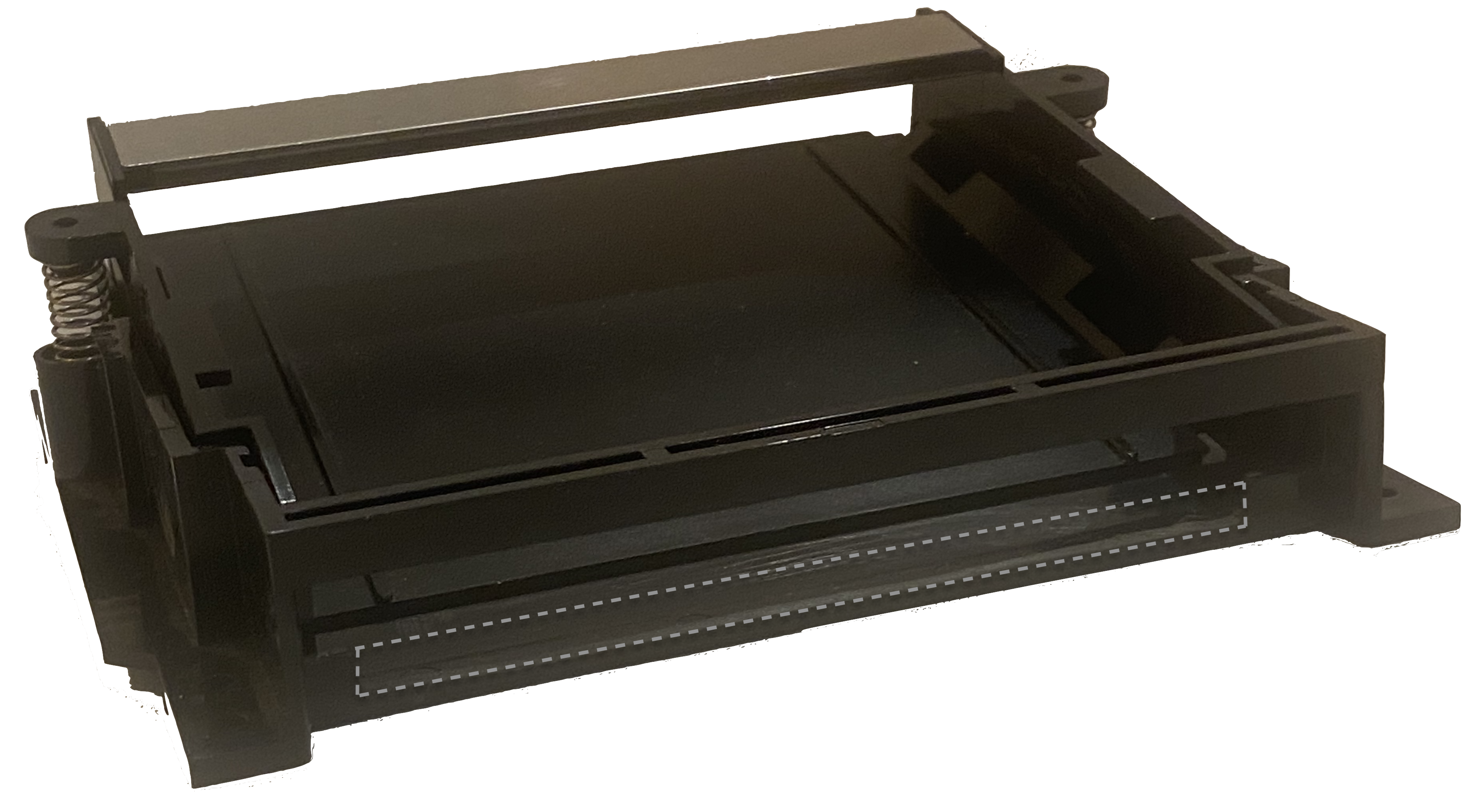 I used a small serrated knife to cut a vertical slice about 9 mm from
the edge on each side. I cut the slice just 1mm short of the bottom.
I then used a dremel with a rotery blade to cut horrizontally between
the vertical slices. This left a 1mm lip across the front of the
cartridg tray. Lastly I sanded down the cut edges.
I used a small serrated knife to cut a vertical slice about 9 mm from
the edge on each side. I cut the slice just 1mm short of the bottom.
I then used a dremel with a rotery blade to cut horrizontally between
the vertical slices. This left a 1mm lip across the front of the
cartridg tray. Lastly I sanded down the cut edges.![[Picture of NES plate]](images/NES-plate.png)
![[Picture of two part NES plate]](images/NES-2part-plate.png) I started by 3D printing a panel that slipped into the metal slot on
top of the cartridge tray. I then began to design legs that would
extend down and trap the edge connector between it and the moving
part of tray. I tried a few designs but in the end concluded I was
not going to be able to reinstall the moving part of the tray and the
arms without cutting away the tray's top support bar. I even tried
to add an up slanting part to the top plate to get up and over the
tray's top support bar. There simply wasn't enough space between
the cartridge tray's top support bar and the cartridge tray's bottom
front for a clip that moves with the tray.
I started by 3D printing a panel that slipped into the metal slot on
top of the cartridge tray. I then began to design legs that would
extend down and trap the edge connector between it and the moving
part of tray. I tried a few designs but in the end concluded I was
not going to be able to reinstall the moving part of the tray and the
arms without cutting away the tray's top support bar. I even tried
to add an up slanting part to the top plate to get up and over the
tray's top support bar. There simply wasn't enough space between
the cartridge tray's top support bar and the cartridge tray's bottom
front for a clip that moves with the tray.![[Picture of NES U clip]](images/NES-U-clip.png)
![[Picture of NES bracket w/ 90 degree ribbon cable connector]](images/NES-bracket-90deg.png) I finally had the idea to make a bracket that would simply trap a
free floating edge connector up against the rounded edge of the
moving part of the tray. The first design had little spring
rockers, but the springs were so small that they did not print well.
Initially I also had a large opening on the back at the top,
leaving space for the pins to stick out of the bottom side of the
PCB, and a hole on the bottom anticipating a 90 degree connector to
accept a ribbon cable.
I finally had the idea to make a bracket that would simply trap a
free floating edge connector up against the rounded edge of the
moving part of the tray. The first design had little spring
rockers, but the springs were so small that they did not print well.
Initially I also had a large opening on the back at the top,
leaving space for the pins to stick out of the bottom side of the
PCB, and a hole on the bottom anticipating a 90 degree connector to
accept a ribbon cable.![[Picture of NES bracket 180 degree ribbon cable connector]](images/NES-bracket-v2.png) It turned out that the edge connector to the NES mainboard did
not leave enough clearance for a 90 degree connector, so I ended up
making the hole for the ribbon connector on the bottom of the back,
and adding a small plate for support on the top covering the opening
for the pins that extend beyond the PCB. I made about 16 revisions,
getting the holes in just the right place, lengthening the front to
back dimension so that it sits flush with the cartridge tray, and
thickening the top cross bar for strength, cutting out notches for
the hinging mechanism on the cartridge tray, and lengthening the
front to back dimension of the top bar to act as a stop and keep the
connector from moving upward more than the required 6 degrees. I made
a prototype of the connector and the board and printed it on the 3D
printer.
It turned out that the edge connector to the NES mainboard did
not leave enough clearance for a 90 degree connector, so I ended up
making the hole for the ribbon connector on the bottom of the back,
and adding a small plate for support on the top covering the opening
for the pins that extend beyond the PCB. I made about 16 revisions,
getting the holes in just the right place, lengthening the front to
back dimension so that it sits flush with the cartridge tray, and
thickening the top cross bar for strength, cutting out notches for
the hinging mechanism on the cartridge tray, and lengthening the
front to back dimension of the top bar to act as a stop and keep the
connector from moving upward more than the required 6 degrees. I made
a prototype of the connector and the board and printed it on the 3D
printer.
NES
              -------
      +5V -- |36   72| -- GND
 CIC toMB <- |35   71| <- CIC CLK
CIC toPak -> |34   70| <- CIC /RST
   PPU D3 <> |33   69| <> PPU D4
   PPU D2 <> |32   68| <> PPU D5
   PPU D1 <> |31   67| <> PPU D6
   PPU D0 <> |30   66| <> PPU D7
   PPU A0 -> |29   65| <- PPU A13
   PPU A1 -> |28   64| <- PPU A12
   PPU A2 -> |27   63| <- PPU A10
   PPU A3 -> |26   62| <- PPU A11
   PPU A4 -> |25   61| <- PPU A9
   PPU A5 -> |24   60| <- PPU A8
   PPU A6 -> |23   59| <- PPU A7
CIRAM A10 <- |22   58| <- PPU /A13
  PPU /RD -> |21   57| -> CIRAM /CE
    EXP 4    |20   56| <- PPU /WR
    EXP 3    |19   55|    EXP 5
    EXP 2    |18   54|    EXP 6
    EXP 1    |17   53|    EXP 7
    EXP 0    |16   52|    EXP 8
     /IRQ <- |15   51|    EXP 9
  CPU R/W -> |14   50| <- /ROMSEL (/A15 + /M2)
   CPU A0 -> |13   49| <> CPU D0
   CPU A1 -> |12   48| <> CPU D1
   CPU A2 -> |11   47| <> CPU D2
   CPU A3 -> |10   46| <> CPU D3
   CPU A4 -> |09   45| <> CPU D4
   CPU A5 -> |08   44| <> CPU D5
   CPU A6 -> |07   43| <> CPU D6
   CPU A7 -> |06   42| <> CPU D7
   CPU A8 -> |05   41| <- CPU A14
   CPU A9 -> |04   40| <- CPU A13
  CPU A10 -> |03   39| <- CPU A12
  CPU A11 -> |02   38| <- M2
      GND -- |01   37| <- SYSTEM CLK
             ---------
https://wiki.nesdev.com/w/index.php/CIC_lockout_chip_pinout
ATtiny13A pinout

                       --------
                       |*     |
                       |1    8| ---------- +5V NES 36
NES 71- CLK----------<-|2    7|->----/RESET -- NES 70
NSE 1 - GND -- LED-----|3    6|-<---/DATAIN -- NES 34
NES 1 - GND -----------|4    5|->--/DATAOut -- NES 35
                       --------

+5V, GND, and reset should connect to cart
the diagram has the accompanying text:![[NESedge-v1.3.1f PCB front side]](images/NESedge-front-v1.3.1f.png)
![[NESedge-v1.3.1f PCB back side]](images/NESedge-back-v1.3.1f.png)
![[NESedge-v1.3.1f cart PC ]](images/NESedge-cart-v1.3.1f.png) I had planned the boards prior to ordering any parts, so I
referenced an IDE ribbon cable I had lying around. I noticed
the bump was on the same side of both connectors and concluded
that the cable was straight through. The ribbon cable comes out
the back of the first PCB, goes behind the second PCB, wraps
around it and plugs in on the far side. I had convinced myself
that because the ribbon cable wraps a round, that the top and
bottom are inverted. While this is strictly speaking true,
it means the bump, and ordering of the rows, will be the same
and not inverted as I had planned. Some how I missed the fact
that a straight through IDE ribbon cable does have a bump on the
same side, but when you fold it over into a U shape, the bumps
are oppsite of each other.
I had planned the boards prior to ordering any parts, so I
referenced an IDE ribbon cable I had lying around. I noticed
the bump was on the same side of both connectors and concluded
that the cable was straight through. The ribbon cable comes out
the back of the first PCB, goes behind the second PCB, wraps
around it and plugs in on the far side. I had convinced myself
that because the ribbon cable wraps a round, that the top and
bottom are inverted. While this is strictly speaking true,
it means the bump, and ordering of the rows, will be the same
and not inverted as I had planned. Some how I missed the fact
that a straight through IDE ribbon cable does have a bump on the
same side, but when you fold it over into a U shape, the bumps
are oppsite of each other.![[NESedg v2 PCB front]](images/NESedge-v2-front.png)
![[NESedg v2 PCB back]](images/NESedge-v2-back.png)
![[NESedg v2 PCB front]](images/NESedge-v2-scraped.png)
![[NESedg v2 PCB back]](images/NESedge-v2.3.1-cart-scraped.png)
![[Picture of NESdge bent jumper pins]](images/NESedge-v2-bent.png) Unfortunately the jumper block for the expansion port plug
board had one row that was hitting a post that holds the NES
mainboard. Since this pin is unused, it didn't matter that
the jumper pin was bent and the jumper clip ripped off. I
made two simple changes in version 3, relocating the expansion
port jumper block,and separating pins 1 and 72.
Unfortunately the jumper block for the expansion port plug
board had one row that was hitting a post that holds the NES
mainboard. Since this pin is unused, it didn't matter that
the jumper pin was bent and the jumper clip ripped off. I
made two simple changes in version 3, relocating the expansion
port jumper block,and separating pins 1 and 72.![[Picture of NES bracket w/ 6 degree uprights]](images/NES-bracket-6deg.png)
![[NESedge logo]](images/NESedge-big_red-white.gif) The final version of the NESedge is version 3.
The NESedge connctor is farily expensive at about $95.00.
The final version of the NESedge is version 3.
The NESedge connctor is farily expensive at about $95.00.
![[NESedg v3 PCB front]](images/NESedge-v3-front.png)
![[NESedg v3 PCB back]](images/NESedge-v3-back.png)
![[NESedg v3 cart PCB]](images/NESedge-v3-cart.png)
![[NESedg v3 cart PCB in bracket]](images/NESedge-v3-cart-bracket.png)
| vendor | Part number | Quantity | Board label | Dscription | URL |
| OSHpark | NESedge-v3-mb-2021-12-28 | 1 | NESedge circuit board that connects to the NES mainboard | https://oshpark.com/shared_projects/j9K7wmCq | |
| OSHpark | NESedge-v3-cart | 1 | NESedge circuit board that connects to the NES cartridge | https://oshpark.com/shared_projects/jmgx1wnL | |
| Samtec | HCSD-36-D-05.00-01-N-G-P72 | 1 | connects to JB1-mb, JB1-cart | IDC ribbon cable, 72-pin, dual row, straight through, 4 inch, 2.54 pitch | https://www.mouser.com/ProductDetail/200-IDSD36D0400G |
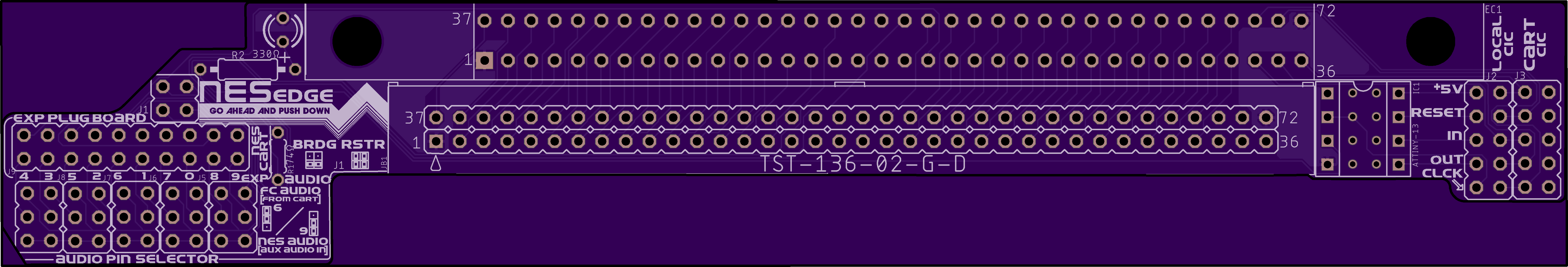
| Samtec | TST-136-02-G-D | 2 | JB1-mb, JB1-cart | 72-pin, dual row, shrouded, IDC PCB header 2.54mm pitch, through hole | https://www.mouser.com/ProductDetail/200-TST13602GD |
| Kingworld | 32827561164 | 2 | EC1-mb, EC1-cart | 72-pin, dual row, edge connctor 2.50mm pitch, through hole | https://www.aliexpress.com/item/32827561164.html |
| TE Connectivity | 5-146269-1 | 1 | J1 | 4-pin, dual row, (2x2) straight, through hole, 2.54mm pitch header | https://www.mouser.com/ProductDetail/571-5-146269-1 |
| TE Connectivity | 826632-5 | 2 | J2-J3 | 10-pin, dual row, (5x2) straight, through hole, 2.54mm pitch header | https://www.mouser.com/ProductDetail/571-826632-5 |
| TE Connectivity | 826632-5 | 5 | J4-J8 | 6-pin, dual row, (3x2) straight, through hole, 2.54mm pitch header | https://www.mouser.com/ProductDetail/649-77313-101-06LF |
| TE Connectivity | 826632-5 | 1 | J9 | 20-pin, dual row, (10x2) straight, through hole, 2.54mm pitch header | https://www.mouser.com/ProductDetail/649-77313-118-10LF |
| Vishay / Beyschiag | MBA02040C4702FRP00 | 1 | R1 | 1/8 watt Metal Film Resistor, Through Hole 0.4watt 47KOhms 1% 3.6mm long | https://www.mouser.com/ProductDetail/594-5063JD47K00FT |
| Vishay / Beyschiag | RN55D3300FB14 | 1 | R2 | 1/8 watt Metal Film Resistor, 330 Ohm 1%m Resistor, Through Hole 0.4watt 47KOhms 1% 3.6mm long | https://www.mouser.com/ProductDetail/71-RN55D3300F |
| VRLite-On | LTL17KTBS3KS | 1 | LED1 | Standard LEDs - Through Hole Blue/ Water Clear 464-476nm1500mcd | https://www.mouser.com/ProductDetail/859-LTL17KTBS3KS |
| Mill-Max | 110-41-308-41-001000 | 1 | IC1 | IC & Component Sockets 8 PIN SKT 200u Sn | https://www.mouser.com/ProductDetail/575-11041308410010 |
| Microchip Technology / Atmel | ATTINY13A-PU | 1 | IC1 | 8-bit Microcontrollers - MCU 1KB In-system Flash 20MHz 1.8V-5.5V | hhttps://www.mouser.com/ProductDetail/556-ATTINY13A-PU |
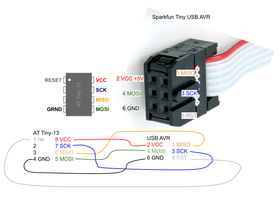
| ATtiny13A Pin | AVR pin | purpose |
| 1 | 5 | Reset |
| 2 | not connected | |
| 3 | not connected | |
| 4 | 6 | Ground |
| 5 | 4 | MOSI |
| 6 | 1 | MISO |
| 7 | 3 | SCK |
| 8 | 2 | VCC |
avrdude -c usbtiny -p t13avrdude: AVR device initialized and ready to accept instructions Reading | ################################################## | 100% 0.01s avrdude: Device signature = 0x1e9007 (probably t13) avrdude: safemode: Fuses OK (E:FF, H:FF, L:6A) avrdude done. Thank you. |
avrdude -c usbtiny -p t13 -U flash:w:avrciczz.elf:eavrdude: AVR device initialized and ready to accept instructions Reading | ################################################## | 100% 0.01s avrdude: Device signature = 0x1e9007 (probably t13) avrdude: NOTE: "flash" memory has been specified, an erase cycle will be performed To disable this feature, specify the -D option. avrdude: erasing chip avrdude: reading input file "avrciczz.elf" avrdude: writing flash (912 bytes): Writing | ################################################## | 100% 0.80s avrdude: 912 bytes of flash written avrdude: verifying flash memory against avrciczz.elf: avrdude: load data flash data from input file avrciczz.elf: avrdude: input file avrciczz.elf contains 912 bytes avrdude: reading on-chip flash data: Reading | ################################################## | 100% 1.94s avrdude: verifying ... avrdude: 912 bytes of flash verified avrdude: safemode: Fuses OK (E:FF, H:FF, L:6A) avrdude done. Thank you. |
avrdude -c usbtiny -p t13 -U lfuse:w:0x70:m -U hfuse:w:0xfb:mavrdude: AVR device initialized and ready to accept instructions Reading | ################################################## | 100% 0.01s avrdude: Device signature = 0x1e9007 (probably t13) avrdude: reading input file "0x70" avrdude: writing lfuse (1 bytes): Writing | ################################################## | 100% 0.02s avrdude: 1 bytes of lfuse written avrdude: verifying lfuse memory against 0x70: avrdude: load data lfuse data from input file 0x70: avrdude: input file 0x70 contains 1 bytes avrdude: reading on-chip lfuse data: Reading | ################################################## | 100% 0.00s avrdude: verifying ... avrdude: 1 bytes of lfuse verified avrdude: reading input file "0xfb" avrdude: writing hfuse (1 bytes): Writing | ################################################## | 100% 0.02s avrdude: 1 bytes of hfuse written avrdude: verifying hfuse memory against 0xfb: avrdude: load data hfuse data from input file 0xfb: avrdude: input file 0xfb contains 1 bytes avrdude: reading on-chip hfuse data: Reading | ################################################## | 100% 0.00s avrdude: verifying ... avrdude: 1 bytes of hfuse verified avrdude: safemode: Fuses OK (E:FF, H:FB, L:70) avrdude done. Thank you. |
![[Picture of NES bracket w/ 6 degree uprights]](images/NES-hi-def.png) If you are looking for an inside the console solution, then Kevtris
Hi-Def NES is probably what you want:
If you are looking for an inside the console solution, then Kevtris
Hi-Def NES is probably what you want:![[Picture of NES bracket w/ 6 degree uprights]](images/retrotink.png)
![[Picture of rad2x cable]](images/rad2x.png)
![[Picture of Open Source Scan Converter]](images/ossc.png)
![[Picture of Everdrive N8 Pro cartridge]](images/everdrive.png) The Everdrive N8 Pro is an FPGA based NES cartridge emulator. It
emulates the memory structure of the NES cartridge then through a menu
driven interface, you can load the ROM into the simulated memory
structure. This allows you to load multiple game ROMs and even save
the game state to reload later. You can down load your entire library
of cartridges and even program your own ROMs.
The Everdrive N8 Pro is an FPGA based NES cartridge emulator. It
emulates the memory structure of the NES cartridge then through a menu
driven interface, you can load the ROM into the simulated memory
structure. This allows you to load multiple game ROMs and even save
the game state to reload later. You can down load your entire library
of cartridges and even program your own ROMs.![[Picture of Everdrive N8 Pro cartridge]](images/light-gun-verter.png) So you want to play those old light gun games on a modern TV? The
light guns such as the NES Zapper, rely on the timing of each scan
line of a Cathode Ray Tube (CRT). When you pull the trigger of the
NES zapper, the screen is blanked out, then a white square is drawn in
the location of each target. If the gun detects white at the time a
target is being drawn, then the appropriate hit is registered. Since
modern TVs draw the screen one screen at time, it has to buffer all of
the scan lines, and then resize the entire image to fit the pixels of the
TV. This means the game has completely finished drawing the screen before
the TV ever displays it, so by the time the light is detected it has
missed the target.
So you want to play those old light gun games on a modern TV? The
light guns such as the NES Zapper, rely on the timing of each scan
line of a Cathode Ray Tube (CRT). When you pull the trigger of the
NES zapper, the screen is blanked out, then a white square is drawn in
the location of each target. If the gun detects white at the time a
target is being drawn, then the appropriate hit is registered. Since
modern TVs draw the screen one screen at time, it has to buffer all of
the scan lines, and then resize the entire image to fit the pixels of the
TV. This means the game has completely finished drawing the screen before
the TV ever displays it, so by the time the light is detected it has
missed the target.![[Picture of NES Toaster]](images/toaster.png)
 NES_edge_v3-mb_2021-12-28
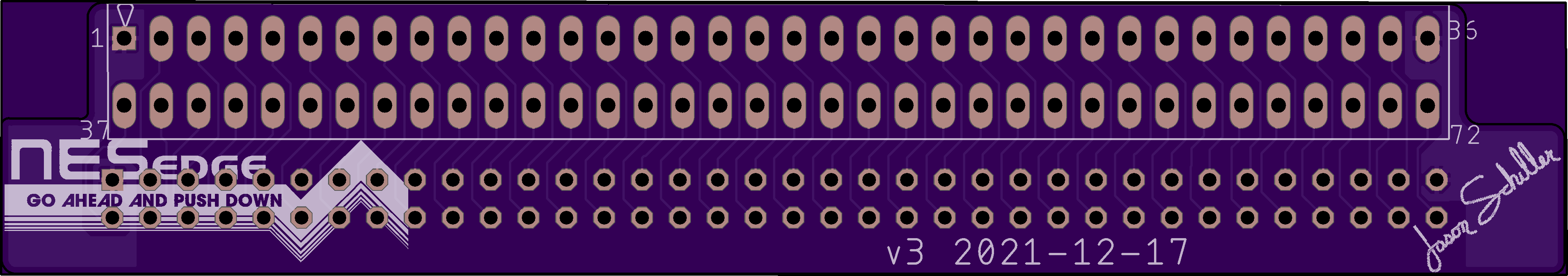 NES_edge v3-cart